

Under contracting work for Valve Corporation, I have been working with Charlie Turner and Andres Gomez from Igalia to develop a CI test farm for driver testing (most graphics).
This is now the fifth CI system I have worked with / on, and I am growing tired of not being able to re-use components from the previous systems due to how deeply-integrated its components are, and how implementation details permeate from one component to another. Additionally, such designs limit the ability of the system to grow, as updating a component would impact a lot of components, making it difficult or even impossible to do without a rewrite of the system, or taking the system down for multiple hours.
With this new system, I am putting emphasis on designing good interfaces between components in order to create an open source toolbox that CI systems can re-use freely and tailor to their needs, while not painting themselves in a corner.
I aim to blog about all the different components/interfaces we will be making for this test system, but in this article, I would like to start with the basics: proposing design goals, and setting up a machine to be controllable remotely by a test system.
Overall design principles
When designing a test system, it is important to keep in mind that test results need to be:
- Stable: Re-executing the same test should yield the same result;
- Reproducible: The test should be runnable on other machines with the same hardware, and yield the same result;
What this means is that we should use the default configuration as much as possible (no weird setup in CI). Additionally, we need to reduce the amount of state in the system to the absolute minimum. This can be achieved in the following way:
- Power cycle the machine between each test cycle: this helps reset the hardware;
- Go diskless if at all possible, or treat the disk as a cache that can be flushed when testing fails;
- Pre-compute as much as possible outside of the test machine, to reduce the impact of the environment of the machine running the test.
Finally, the machine should not restrict which kernel / Operating System can be loaded for testing. An easy way to achieve this is to use netboot (PXE), which is a common BIOS feature allowing diskless machines to boot from the network.
Converting a machine for testing
Now that we have a pretty good idea about the design principles behind preparing a machine for CI, let’s try to apply them to an actual machine.
Step 0: Select machines without internal batteries
While laptops and other hand-held devices are compact devices you may already have available, they can be tricky to power cycle. They may not boot once the battery gets disconnected, their performance may be degraded, or they may outright crash when under stress as the battery isn’t there to smooth out the power rails, leading to brownouts…
Your time is valuable, and this is especially true if this is your first experience with a bare-metal CI system. I would suggest start with x86-based single-board computers, or (small-form-factor?) desktop PCs if at all possible. As an example, if you wanted to test Apple Silicon, I would recommend sourcing Mac Minis rather than a Macbook Air.
Anyway, if you decide to go forward with a battery-powered machine, the first step is simply to attempt booting it with the battery disconnected. Be really patient as the machine may take longer to boot than usual due to the embedded controller repeatedly failing to communicate with the now-disconnected battery. This can take a minute or two…
If the machine did manage to boot up, congratulations! You will now need to verify that its performance is unaffected by the change, and that it remains stable. A quick and easy check would be to run the following stress test while checking which CPU frequencies were reached by the CPU:
$ stress -c `nproc` -i 10 -d 5 -t 120
If the test passed, consider yourself lucky! You may want to proceed with this tutorial!
However, if the boot fails/takes too long, or if the machine is not operating at its expected performance or reliability, all is not lost. Check out your options in our dedicated entry in the FAQ.
Step 1: Powering up the machine remotely
In order to power up, a machine often needs both power and a signal to start. The latter is usually provided by a power button, but additional ways exist (non-exhaustive):
- Wake on LAN: An Ethernet frame sent to the network adapter triggers the boot;
- Power on by Mouse/Keyboard: Any activity on the mouse or the keyboard will boot the computer;
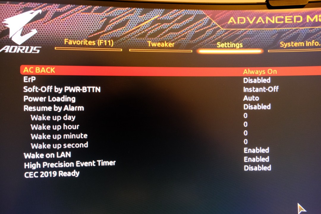
- Power on AC: Providing power to the machine will automatically turn it on;
- Timer: Boot at a specified time.

Unfortunately, none of these triggers can be used to also turn off the machine. The only way to guarantee that a machine will power down and reset its internal state completely is to cut its power supply for a significant amount of time. A safe way to provide/cut power is to use a remotely-switchable Power Distribution Unit (example), a managed ethernet switch with per-port switchable PoE (Power over Ethernet) ports, or simply using some smart plug such as Shelly plugs or Ikea’s TRÅDFRI. In any case, make sure you rely on as few services as possible (no cloud!), that you won’t exceed the ratings of the power supply (voltage, power, and cycles), and can read back the state to make sure the command was well received. If you opt out for the industrial PDUs, make sure to check out PDU Gateway, our REST service to control the machines.

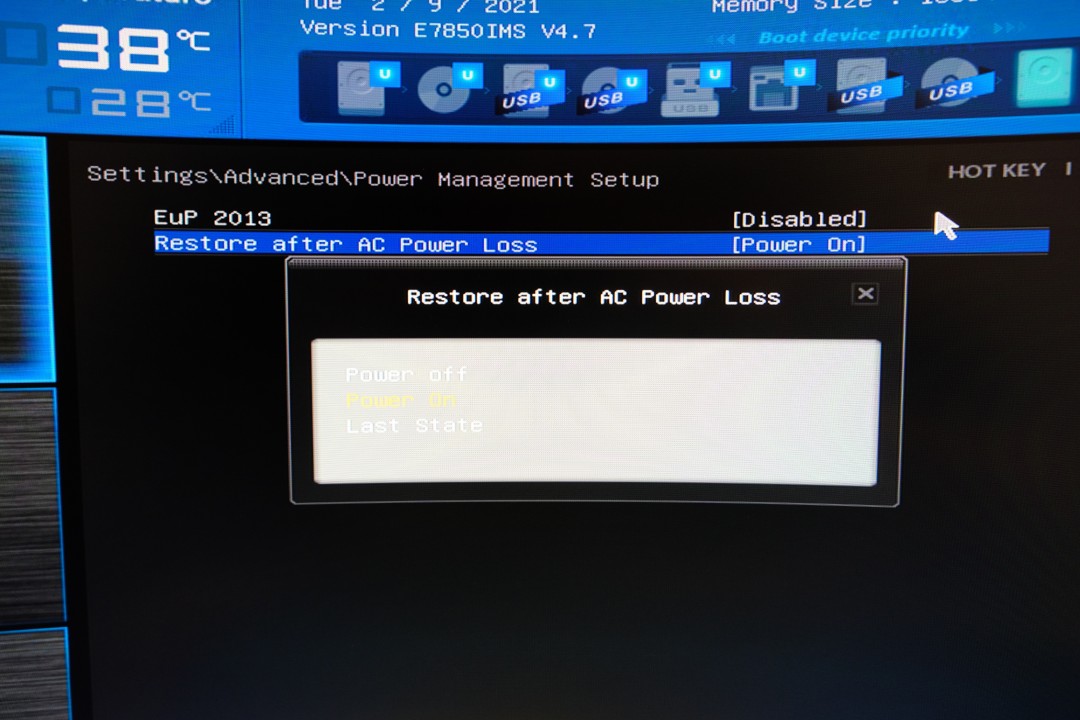
Now that we can reliably cut/provide power, we still need to control the boot signal. The difficulty here is that the signal needs to be received after the machine received power and initialized enough to receive this event. To make things as easy as possible, the easiest is to configure the BIOS to boot as soon as the power is brought to the computer. This is usually called “Boot on AC”. If your computer does not support this feature, you may want to try the other ones, or use a microcontroller to press the power button for you when powering up (see the HELP! My machine can’t … Boot on AC section at the end of this article).
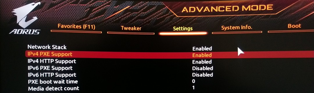
Step 2: Net booting
Net booting is quite commonly supported on x86 and ARM bootloaders.
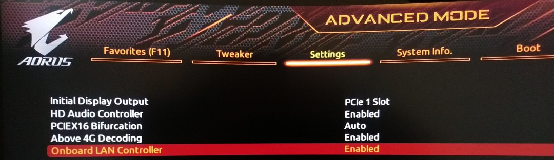
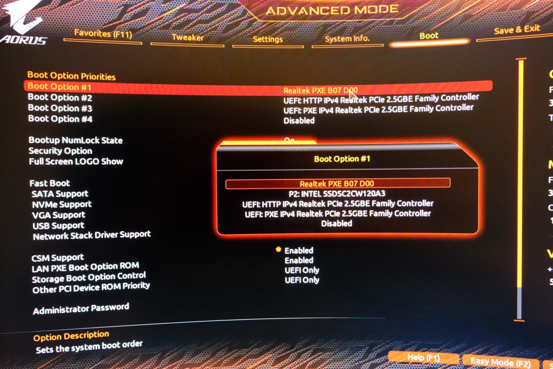
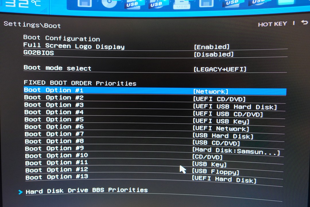
On x86 platforms, you can generally find this option in the boot option priorities
under the name PXE boot or network boot. You may also need to enable the
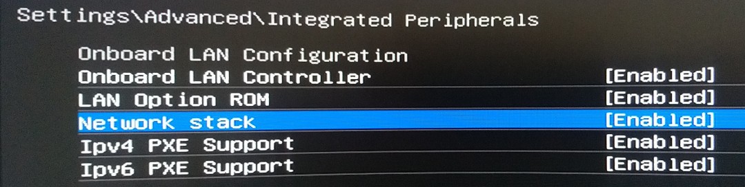
LAN option ROM, LAN controller, or the UEFI network stack. Reboot, and
check that your machine is trying to get an IP!
On ARM/RiscV platforms, the board’s bootloader may already default to PXE booting when no bootable media is found (see Raspberry Pi’s boot sequence). Don’t panic if your board doesn’t do it by default, you’ll just need to install one that will do the job:
- Modern:
- barebox: A POSIX/Linux-like interface, but few boards supported;
- tow-boot: Good support for the popular SBCs, sane defaults, good UI;
- tianocore / EDK2: Full-UEFI environment, nice UI, but slow to boot;
- Old-school:
- u-boot: Widest boards compatibility, good feature-set, but only works with small kernels. Use as a last resort!
The next step will be to set up a machine, called Testing Gateway, that will provide a PXE service. This machine should have two network interfaces, one connected to a public network, and one connected to the test machines (through a switch). Setting up this machine will be the subject of an upcoming blog post, but if your are impatient, you may use our valve-infra container or the simpler netboot2container.
Step 3: Emulating your screen and keyboard using a serial console
Thanks to the previous steps, we can now boot in any Operating System we want, but we cannot interact with it…
One solution could be to run an SSH server on the Operating System, but until we could connect to it, there would be no way to know what is going on. Instead, we could use an ancient technology, a serial port, to drive a console. This solution is often called “Serial console” and is supported by most Operating Systems. Serial ports come in two types:
- UART: voltage changing between 0 and VCC (TTL signalling), more common in the System-on-Chip (SoC) and microcontrollers world;
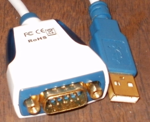
- RS-232: voltage changing between a positive and negative voltage, more common in the desktop and datacenter world.
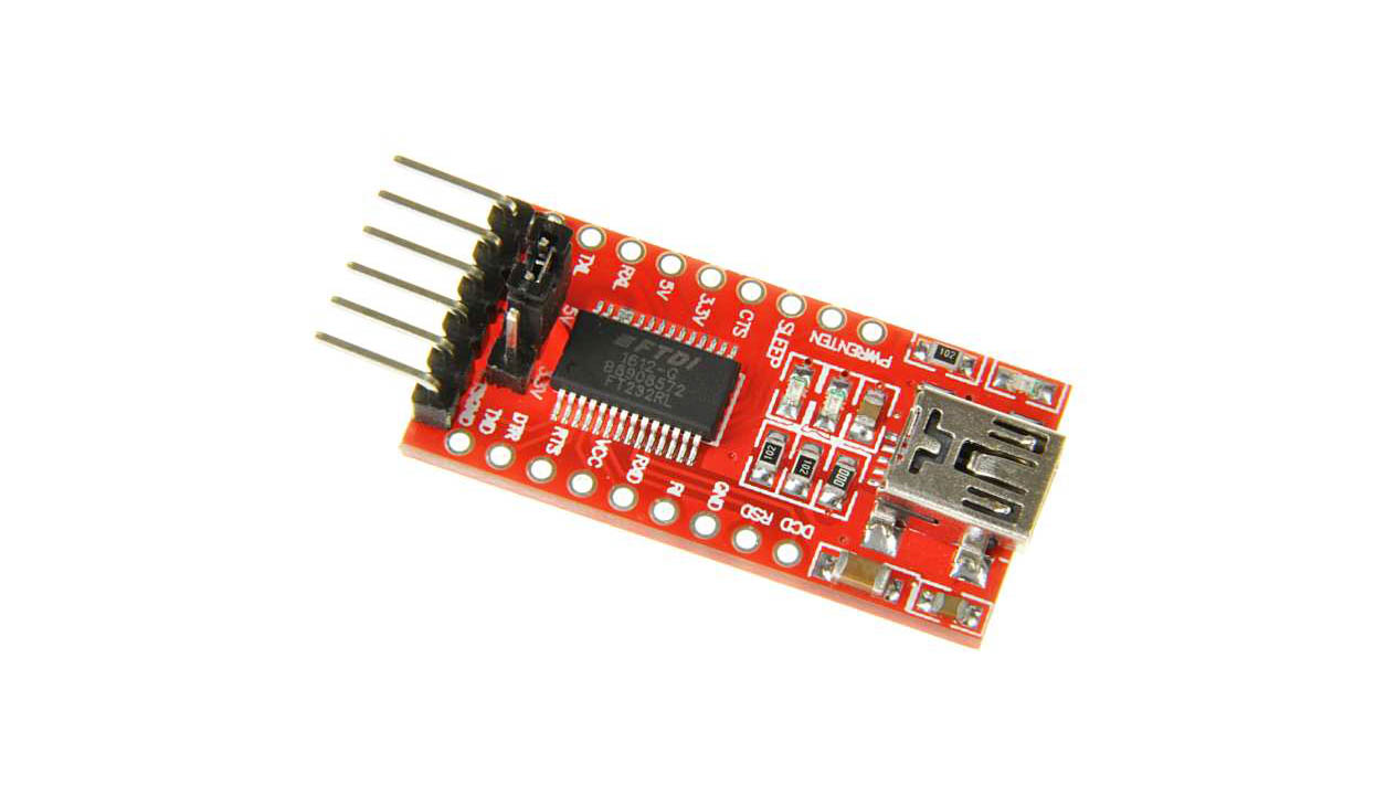
In any case, I suggest you find a serial-to-USB adapter adapted to the computer you are trying to connect:
On Linux, using a serial console is relatively simple, just add the following
in the command line to get a console on your screen AND over the /dev/ttyS0
serial port running at 9600 bauds:
console=tty0 console=ttyS0,9600 earlyprintk=vga,keep
If your machine does not have a serial port but has USB ports, which is more the norm than the exception in the desktop/laptop world, you may want to connect two RS-232-to-USB adapters together, using a Null modem cable:
Test Machine <-> USB <-> RS-232 <-> NULL modem cable <-> RS-232 <-> USB Hub <-> Gateway
And the kernel command line should use ttyACM0 / ttyUSB0 instead of ttyS0.
Putting it all together
Start by removing the internal battery if it has one (laptops), and any built-in wireless antenna. Then set the BIOS to boot on AC, and use netboot.
Steps for an AMD motherboard:
Steps for an Intel motherboard:
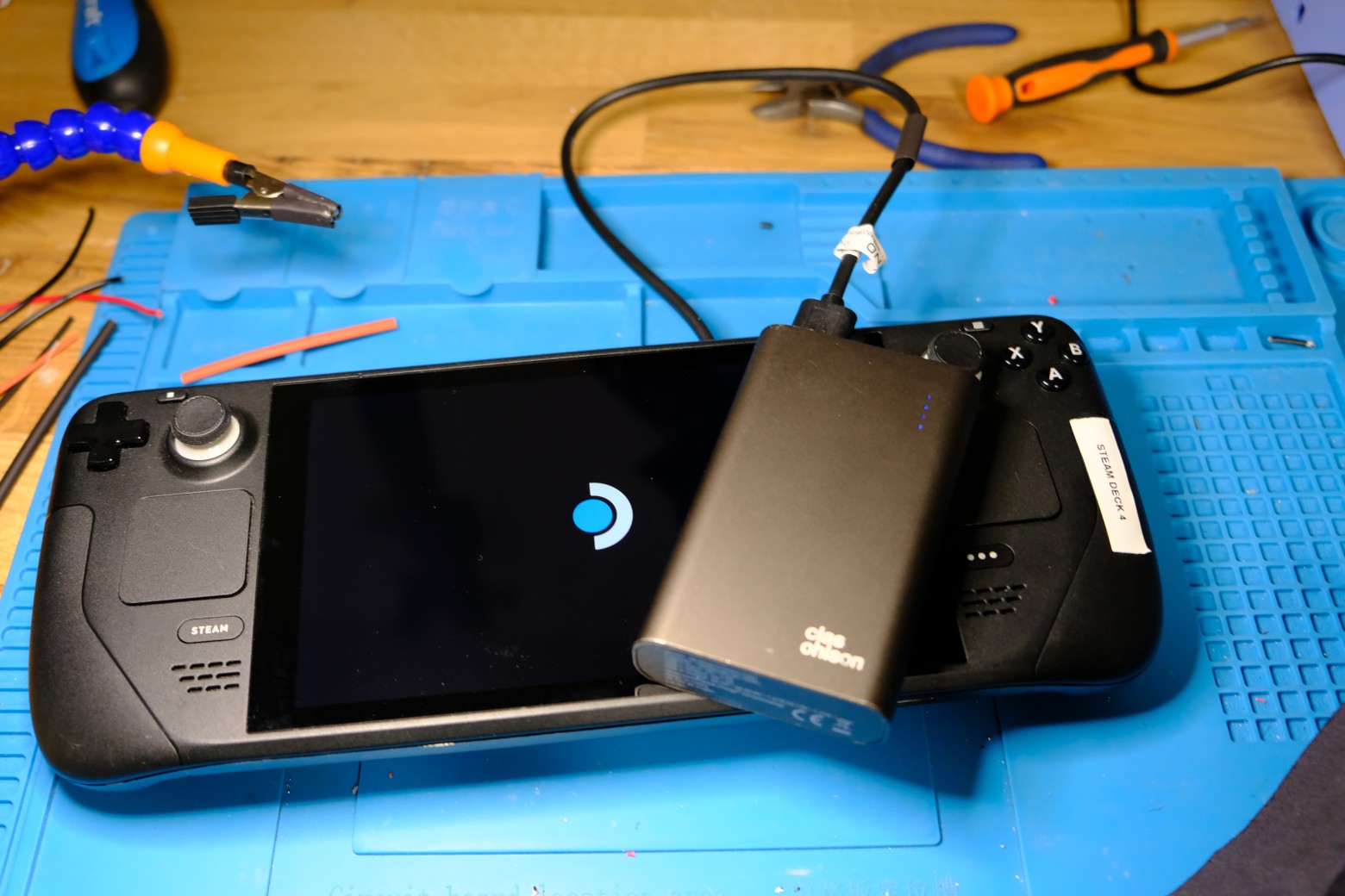
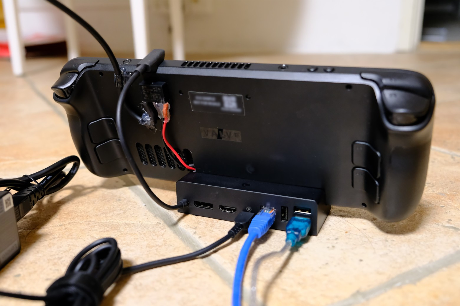
Finally, connect the test machine to the wider infrastructure in this way:

If you managed to do all this, then congratulations, you are set! If you got some issues with any of the previous steps, brace yourself, and check out the following section!
HELP! My machine can’t …
Net boot
It’s annoying, but it is super simple to work around that. What you need is to install a bootloader on a drive or USB stick which supports PXE.
I would recommend you look into iPXE, as it is super easy to setup and amazingly versatile!
Boot on AC
Well, that’s a bummer, but that’s not the end of the line either if you have some experience dealing with microcontrollers, such as Arduino. Provided you can find the following 4 wires, you should be fine:
- Ground: The easiest to find;
- Power rail: 3.3 or 5V depending on what your controller expects;
- Power LED: A signal that will change when the computer turns on/off;
- Power Switch: A signal to pull-up/down to start the computer.
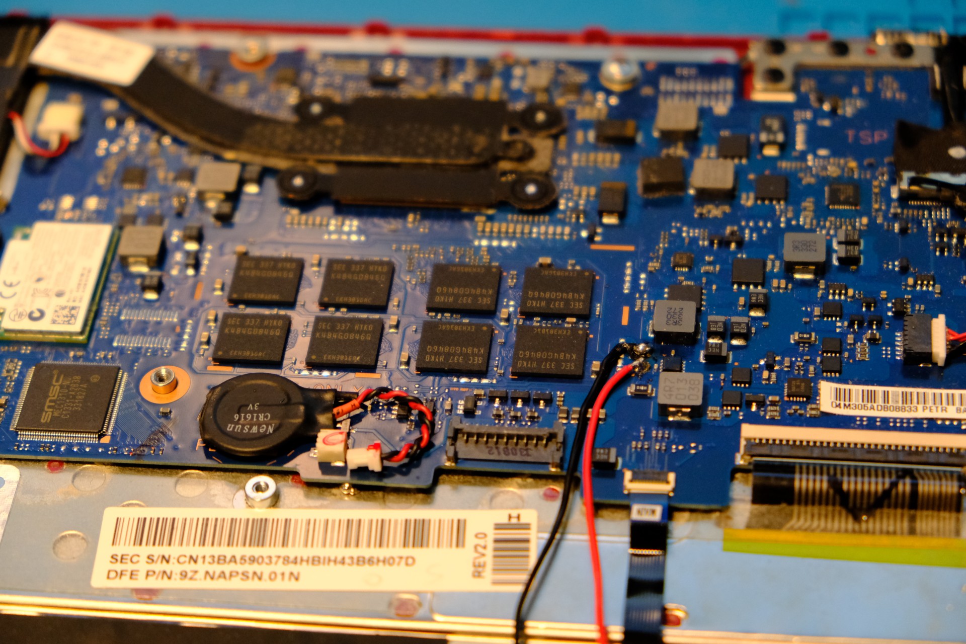
On desktop PCs, all these wires can be easily found in the motherboard’s manual. For laptops, you’ll need to scour the motherboard for these signals using a multimeter. Pay extra attention when looking for the power rail, as it needs to be able to source enough current for your microcontroller. If you are struggling to find one, look for the VCC pins of some of the chips and you’ll be set.
Next, you’ll just need to figure out what voltage the power LED is at when the machine is ON or OFF. Make sure to check that this voltage is compatible with your microcontroller’s input rating and plug it directly into a GPIO of your microcontroller.
Let’s then do the same work for the power switch, except this time we also need to check how much current will flow through it when it is activated. To do that, just use a multimeter to check how much current is flowing when you connect the two wires of the power switch. Check that this amount of current can be sourced/sinked by the microcontroller, and then connect it to a GPIO.
Finally, we need to find power for the microcontroller that will be present as soon as we plug the machine to the power. For desktop PCs, you would find this in Pin 9 of the ATX connector. For laptops, you will need to probe the motherboard until you find a pin that has one with a voltage suitable for your microcontroller (5 or 3.3V). However, make sure it is able to source enough current without the voltage dropping bellow the minimum acceptable VCC of your microcontroller. The best way to make sure of that is to connect this rail to the ground through a ~100 Ohm and check that the voltage at the leads of the resistor, and keep on trying until you find a suitable place (took me 3 attempts). Connect your microcontroller’s VCC and ground to the these pads.
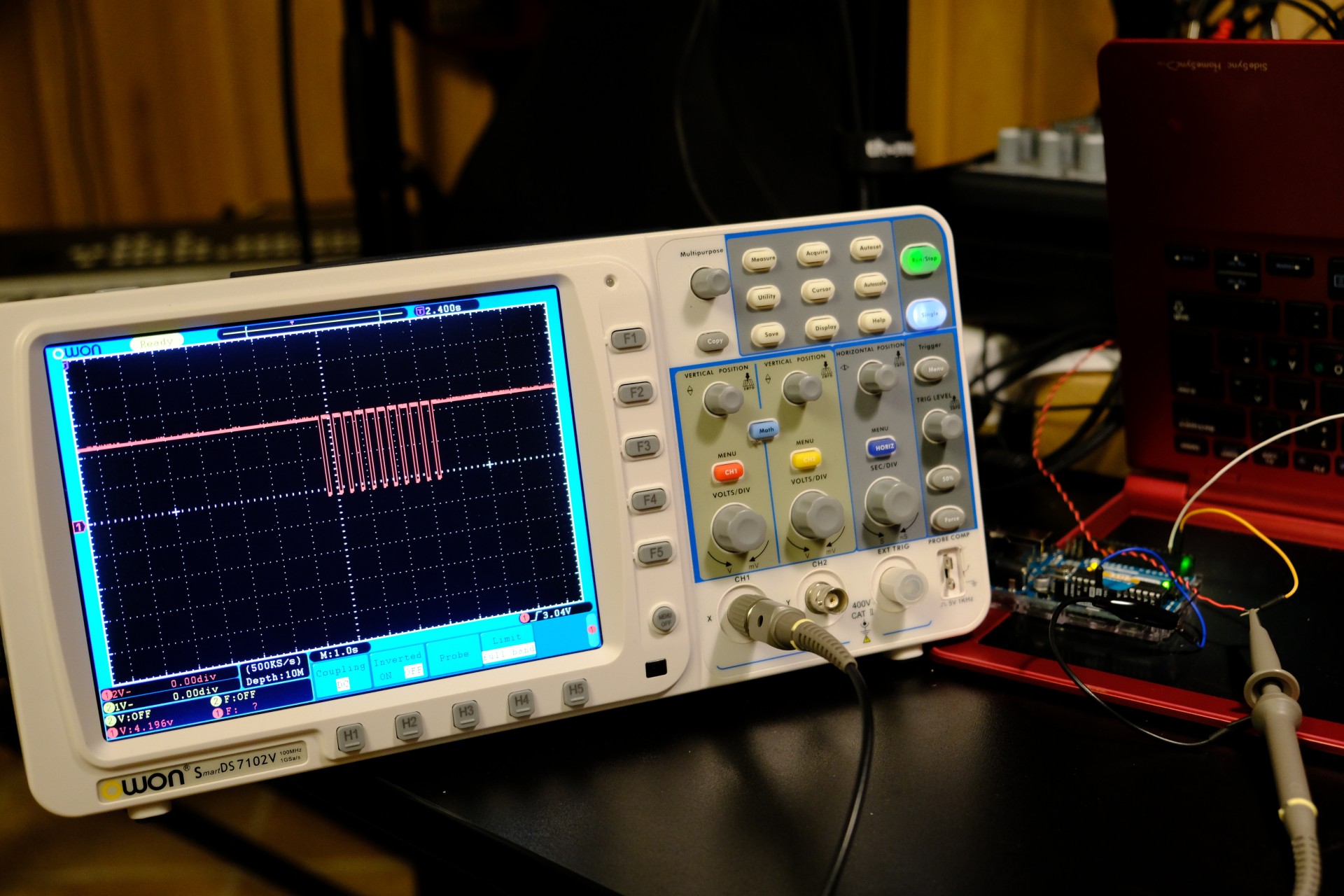
The last step will be to edit this Arduino code for your needs, flash it to your microcontroller, and iterate until it works!
Here is a photo summary of all the above steps:
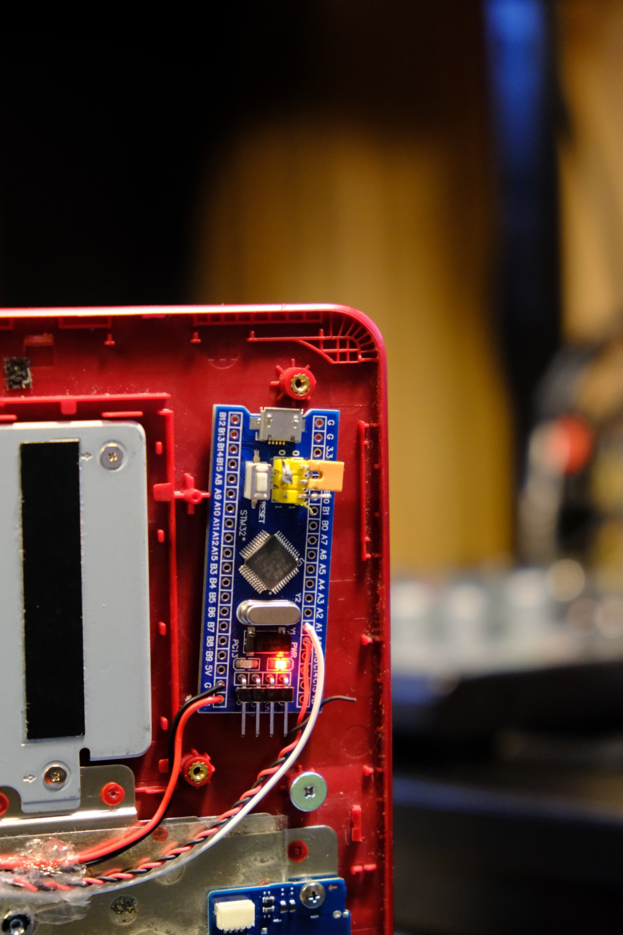
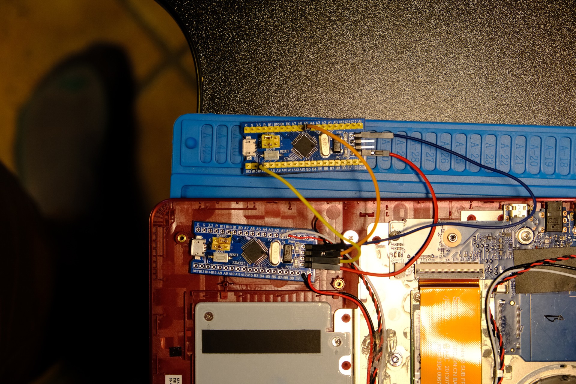
Thanks to Arkadiusz Hiler for giving me a couple of these BluePills, as I did not have any microcontroller that would be small-enough to fit in place of a laptop speaker. If you are a novice, I would suggest you pick an Arduino nano instead.
Oh, and if you want to create a board that would be generic-enough for most motherboards, check out the schematics from my almost-decade-old blog post about doing just that!
Boot / run normally (slow/unreliable) without a battery
Before going any further, I would really urge you to reconsider your decision to use this machine for CI. If there are no other alternatives, don’t despair, things will be …. juuuuuust fine!

Since we want our test machines to behave in the same way as users’, we should strive for minimizing the impact of our modifications to the machine.
When it comes to the internal battery, we ideally want it to be connected while the machine is running (mirroring how users would use the machine), and disconnected between test jobs so as to minimize the chances of any state leaking between jobs which would affect reproducibility of results.
We can achieve this goal at two levels: in software by hacking on the embedded controller, or physically by modifying the power-delivery.
1. Hack the Embedded Controller (EC)
If your device’s firmware or embedded controller (EC) is open source, you should be able to monitor the state of the power supply, and you probably can find a way to turn off the machine (the routine called when pressing the power button for 10s) when the main power supply is disconnected.
Unfortunately, the only devices with open source EC I am aware of are chromebooks, so your only choice may be to…
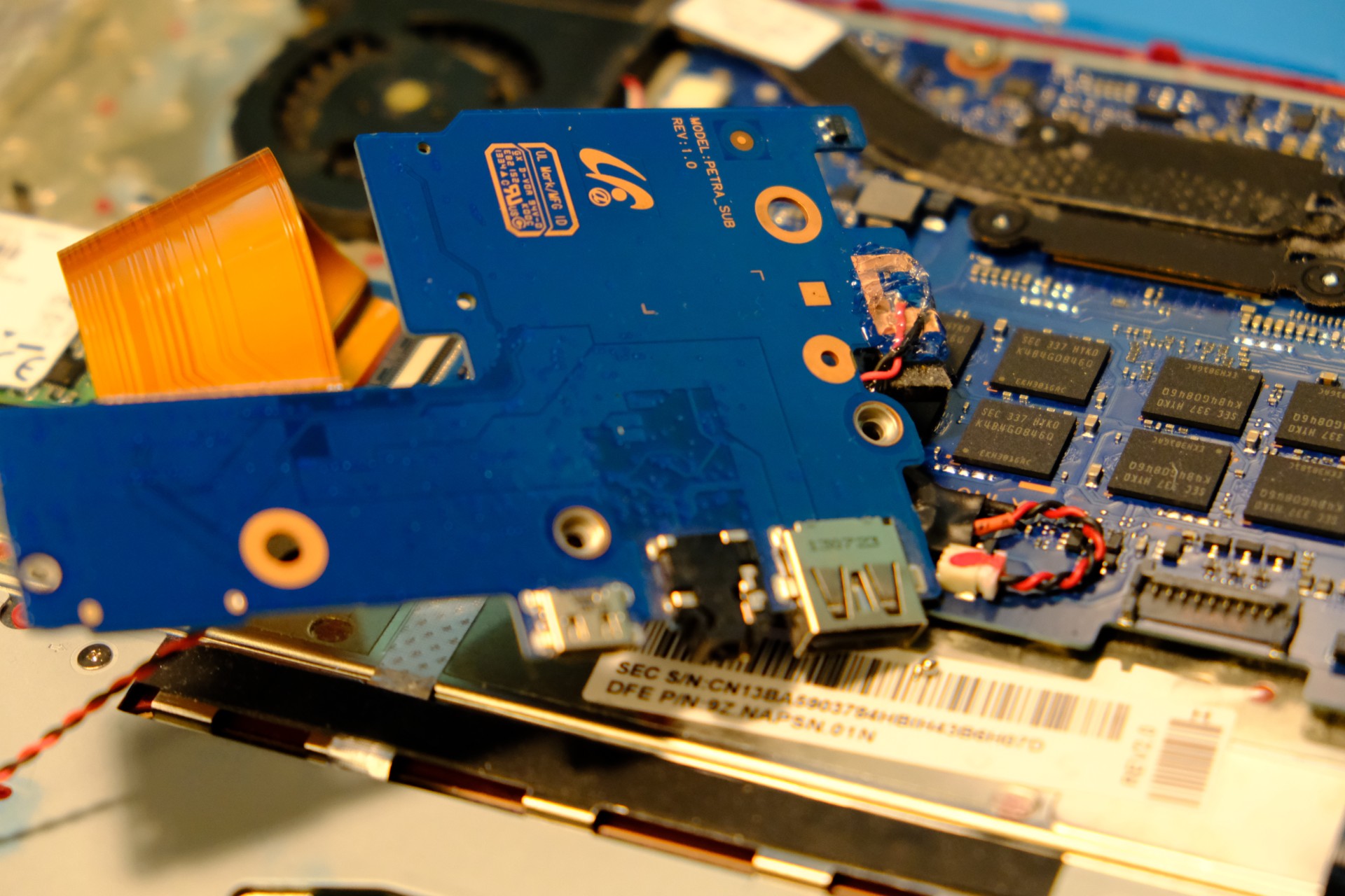
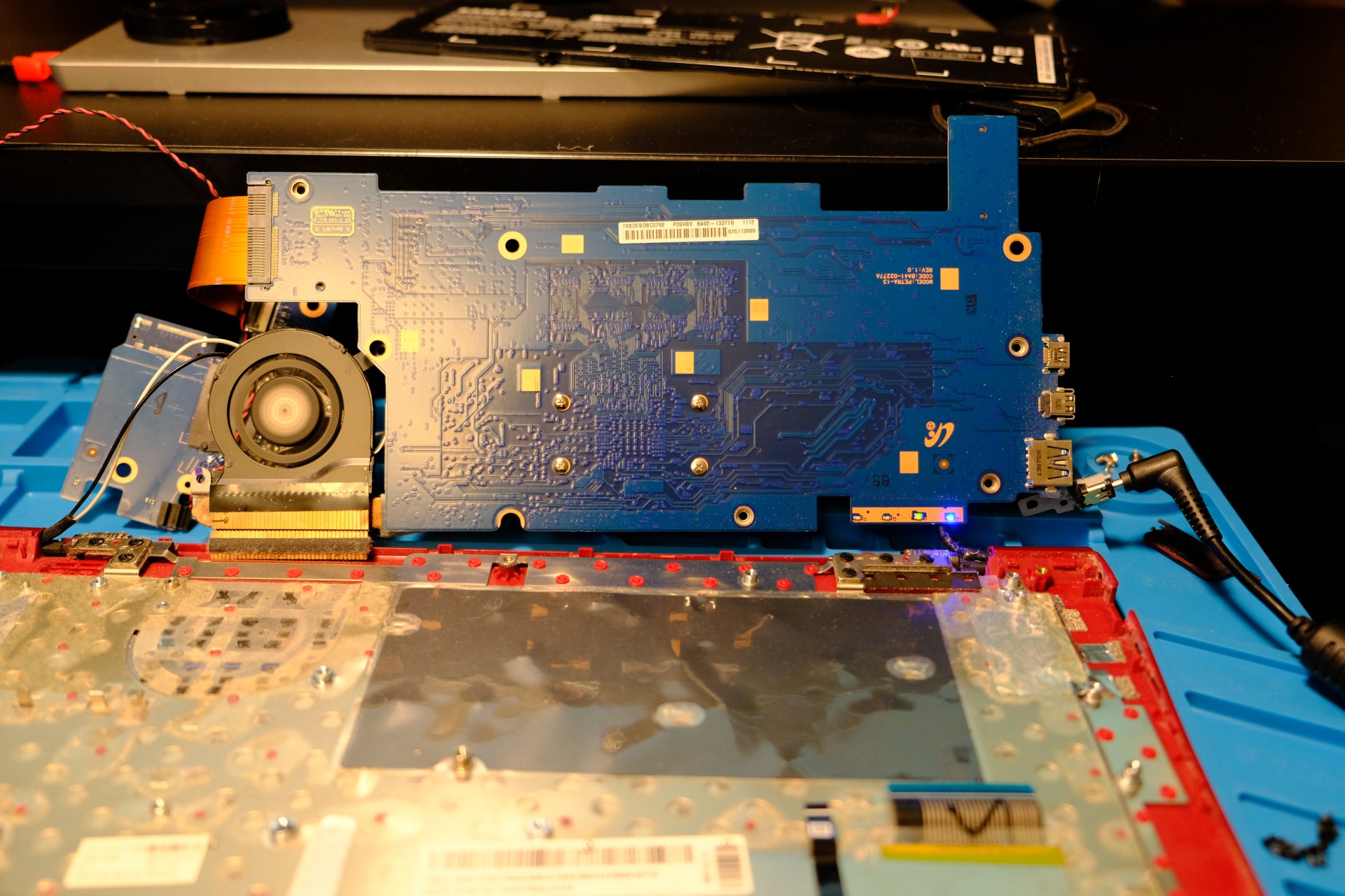
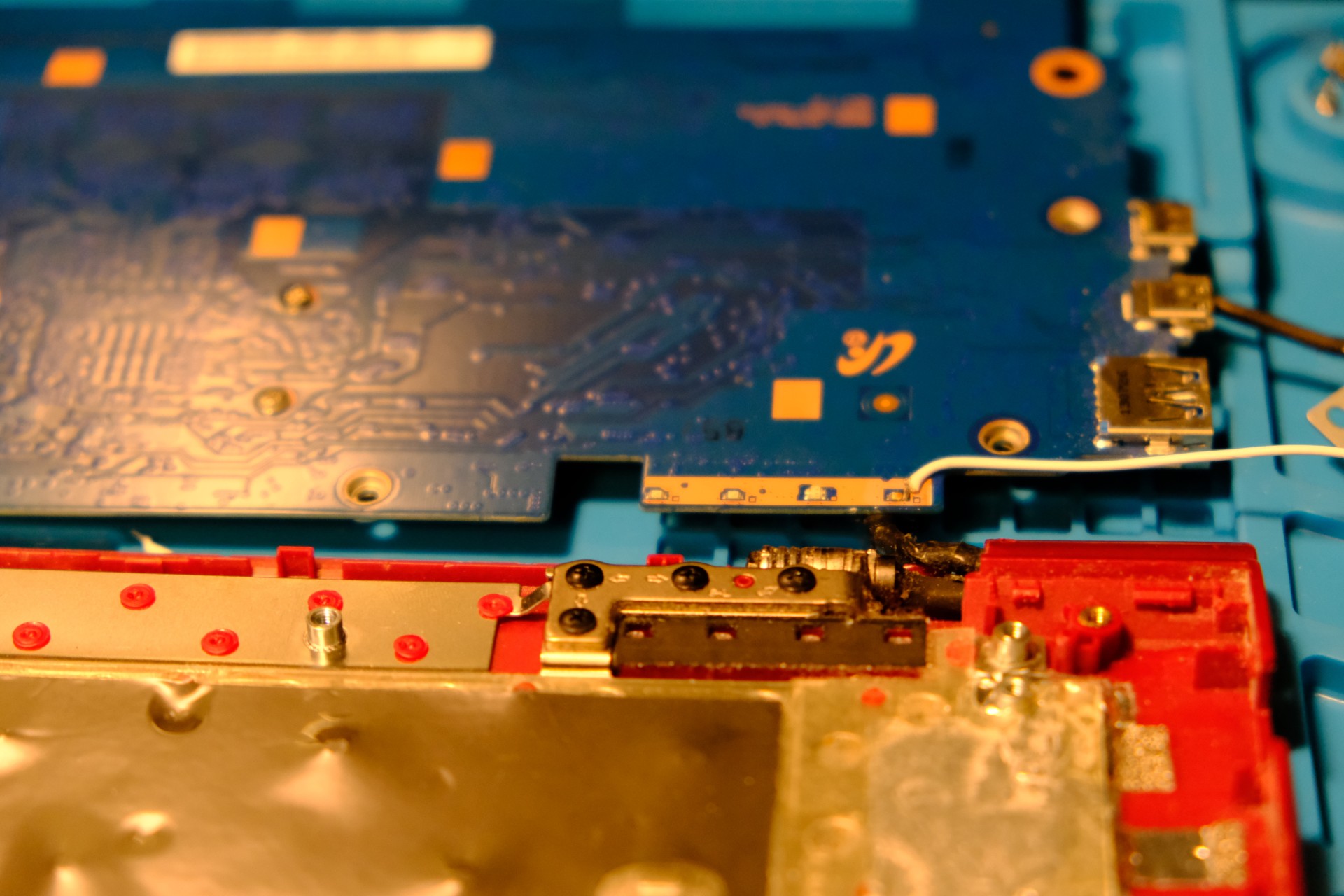
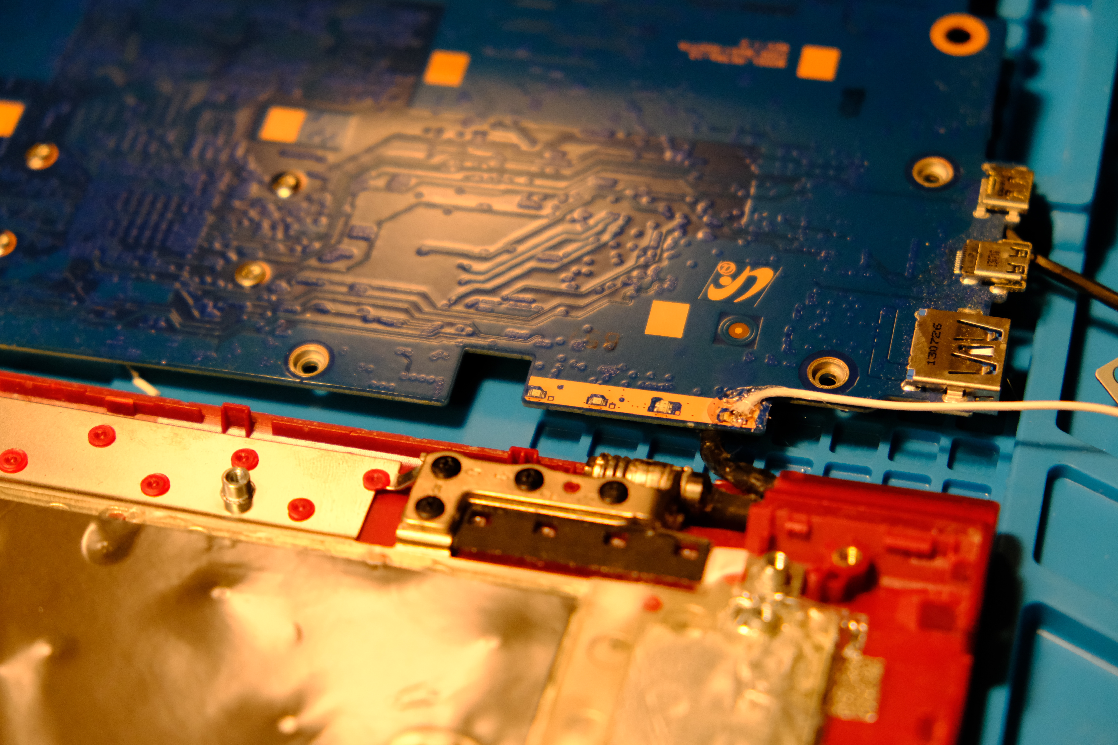
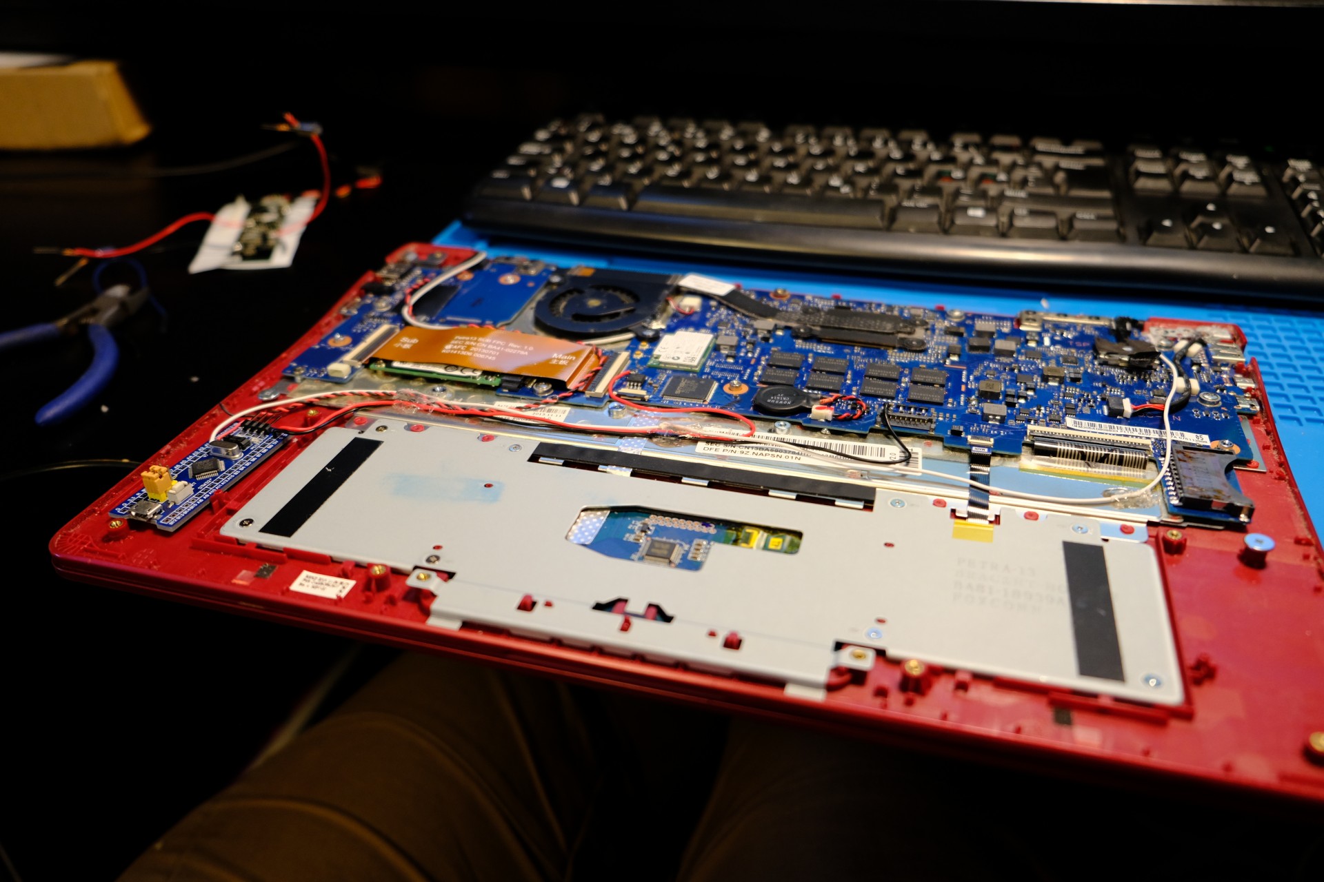
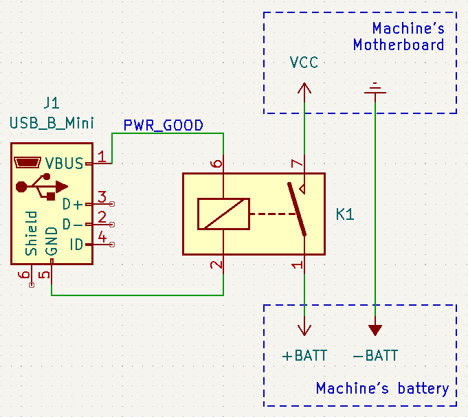
2. Instrument the machine’s power delivery
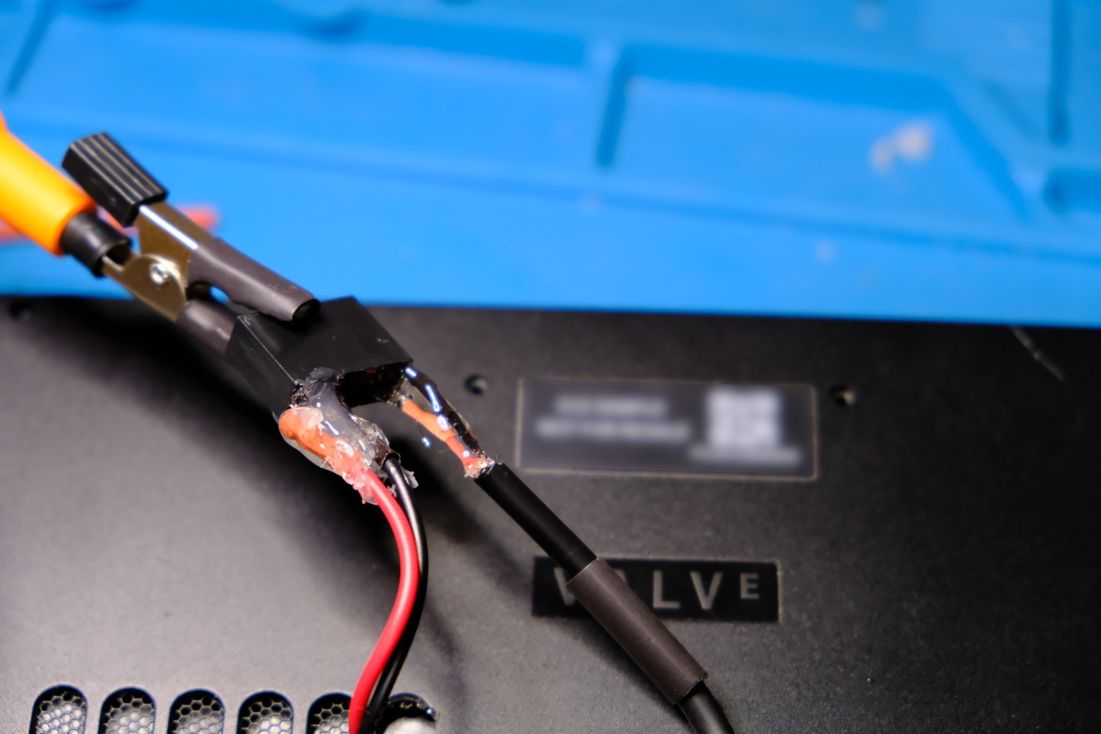
If we can’t get the embedded controller to do the work for us, we can do the same using a 5V relay with a normally-open contact, a few wires, a soldering iron, and an old USB power supply!
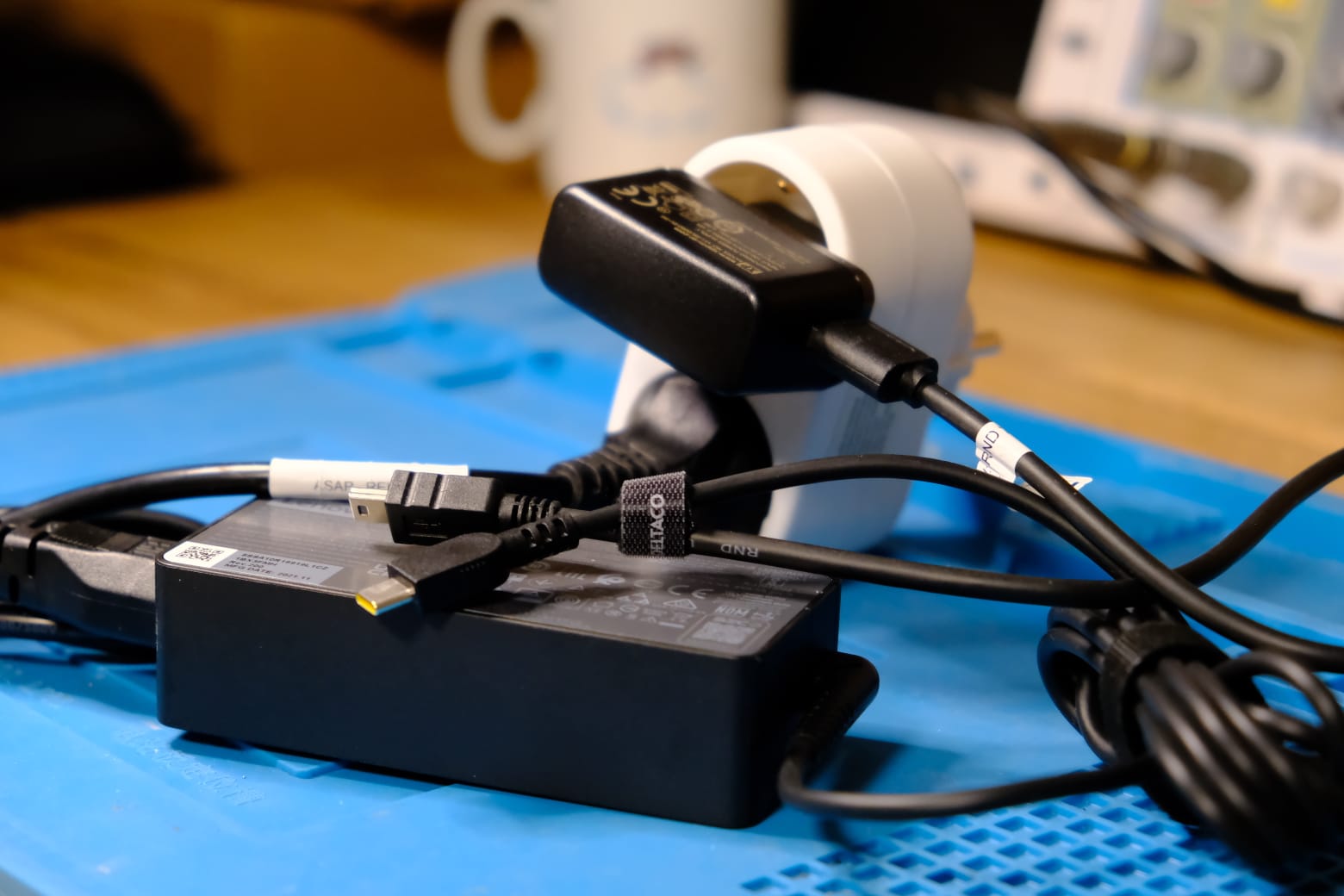
The first step is to figure out a way to detect whether the power supply is connected or not. The foolproof way is to use use an old USB charger, connected to the same PDU port as the machine’s power supply. This will provide us with a 5V power supply when the machine is supposed to be ON, and 0V otherwise.
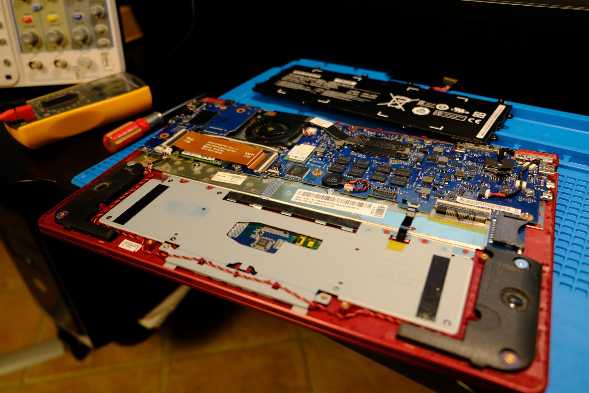
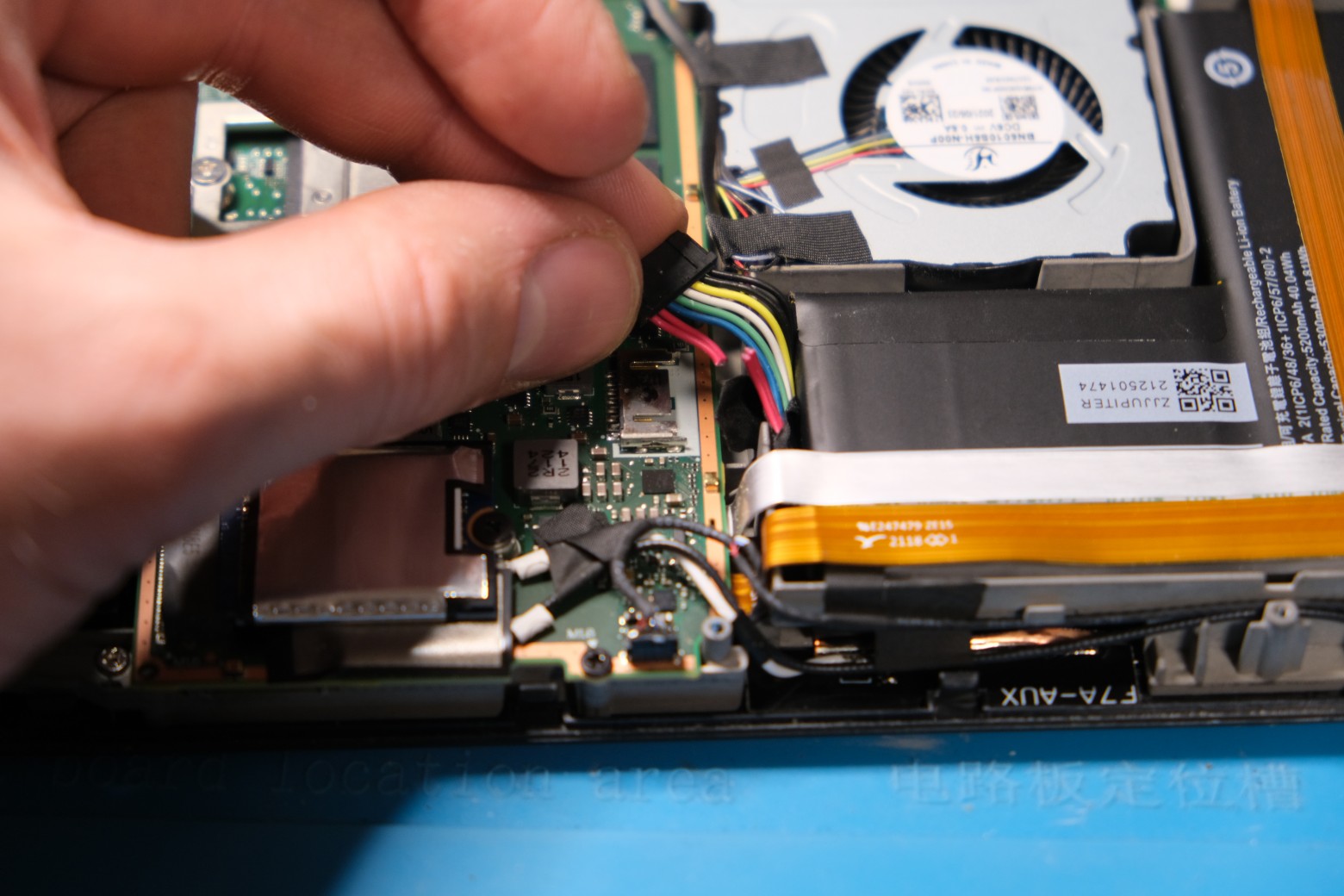
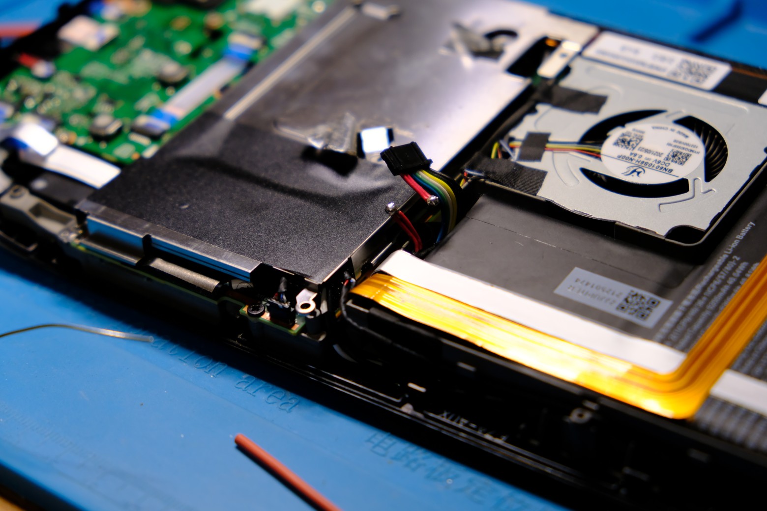
- Disconnect the power to the machine
- Open up the machine enough to access its main PCB and battery
- Disconnect the battery
- Identify the negative and positive leads of the battery using a voltmeter
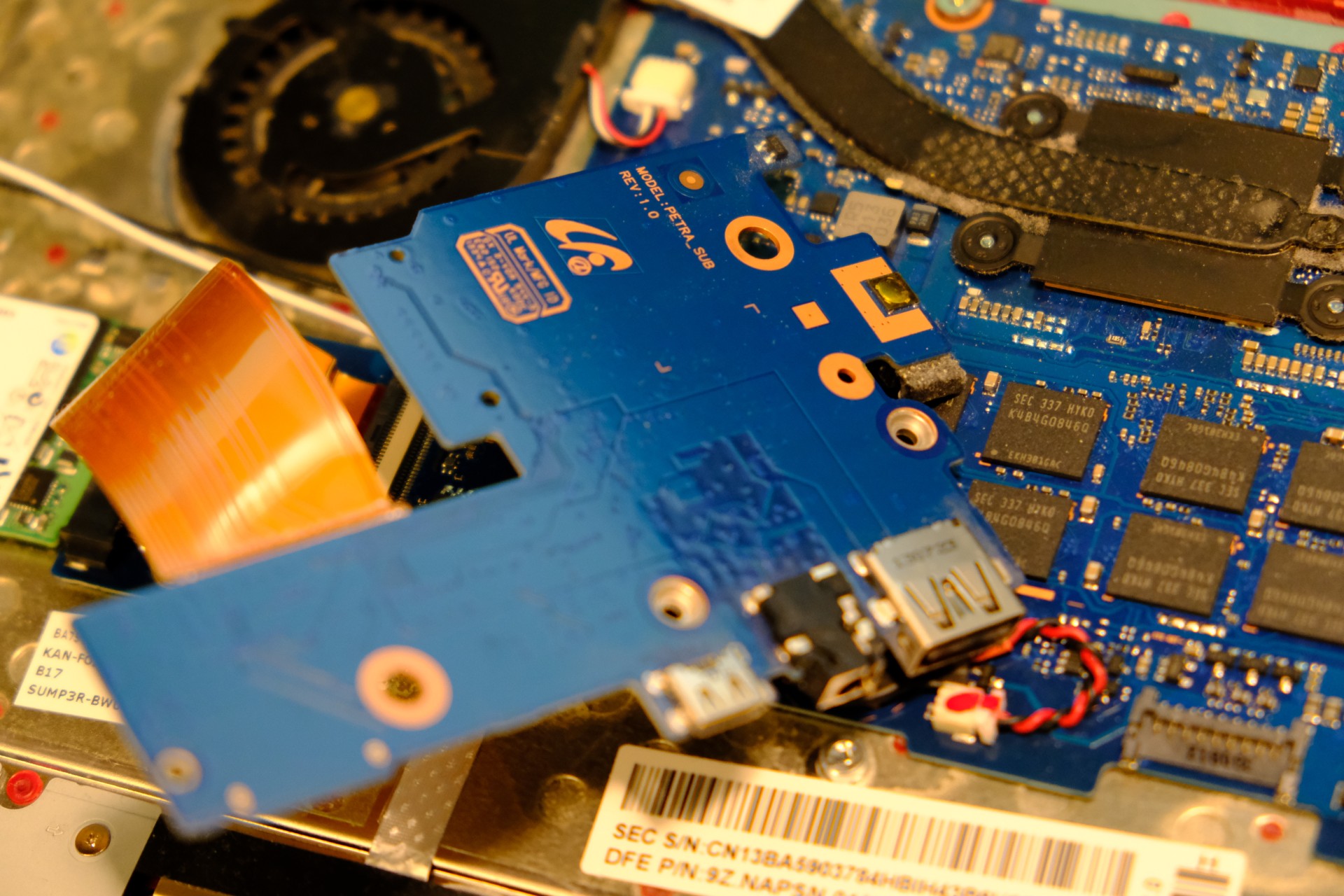
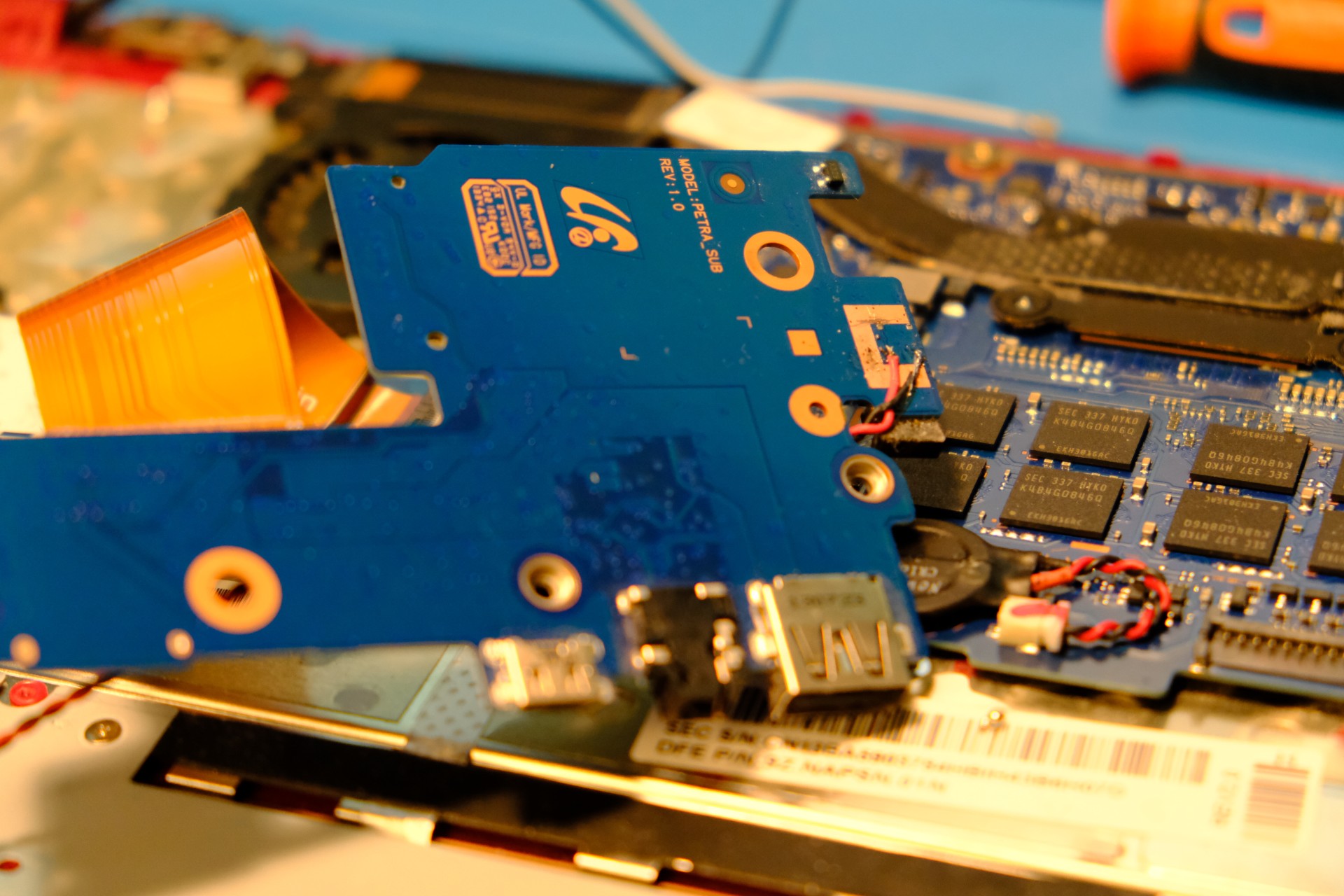
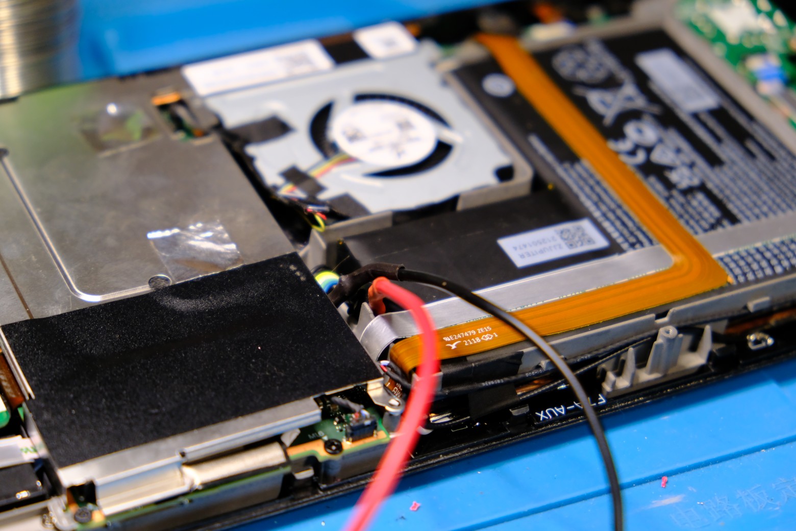
- Cut the positive lead(s)
- Solder extension wires to both sides
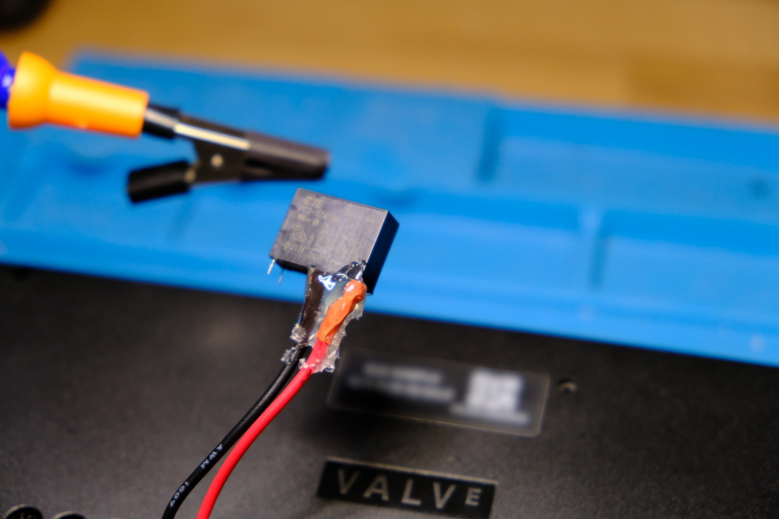
- Solder them to the normally-open contacts of your 5V relay
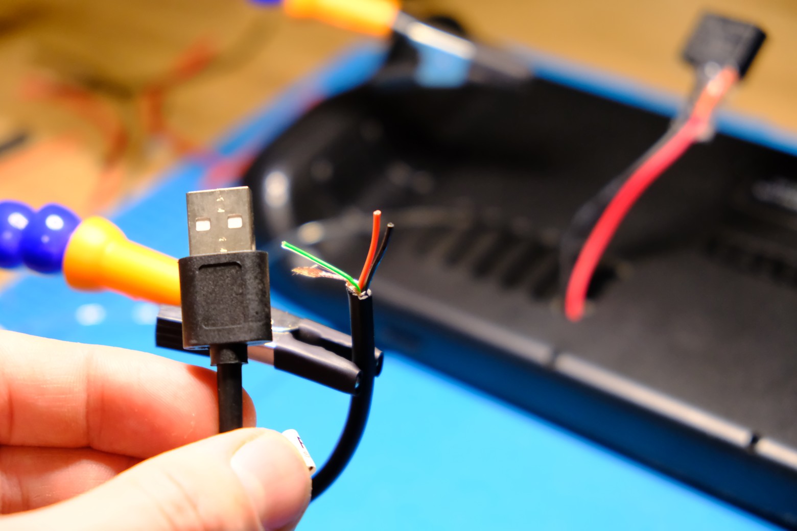
- Solder the coil leads of the relay to an old USB-A cable
- Secure everything with heatshrink and hotglue
- Close the machine and test it
That’s all, folks!